This adventure started out with a potato gun very much like this:
The difference was the chamber (the grey part) was 32 inches long instead of 21.
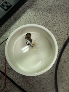
The predicted velocity for this gun is 411.6 mph. The actual velocity was not measured, but it could have been a lot lower. At the end of the gun was this end cap:
This is the barbeque ignitor and cap that screws into the end of the chamber that contains the fuel / air mixture. The epoxied ignitor wires are attached to a spark gap that maintains a spark when the red button is pushed.
First feed the red wire through a hole drilled in the end cap.
Then feed the black wire.
 Cut the end of the tabbed end of the red wire.
Cut the other end of the black wire.
Use wire strippers shown above to strip the ends of the red and black wire that were cut.

Solder the red wire to the end of the ignitor and solder the black wire to the metal tab on the side of the
ignitor.
Then epoxy the wires in place so that it looks like above. Please note that this cap is different because it is a another design that cemented on a end cap to the chamber. Fuel was added through an opening where the barrel screws on instead of through the end cap.
This is the second gun that was built, and perhaps was one of the best performers. It happily sent a potato sailing through a box...
and into many pieces along the wall...taking the paint with it.
Cans were dented substantially and became airborne.
Windshields were cracked...
An even larger gun was hauled by Mazda Miata...
This one did some damage...
A gun with four screw on barrels was also constructed...
The chamber was constructed out of 4 inch diameter pipe in a 21 inch segment. One end had a rounded end cap that is pictured below.
The other end had a 4 inch to 2 inch reducer which was attached to a a 2 inch female coupling. This female coupling could be attached to a 2 inch male coupling that either had an attached 2 inch to 3/4 inch reducer bushing or a 2 inch pipe. The 2 inch pipe could be either 4 feet or 6 feet long. The 3/4 inch reducer bushing was attached to a 3/4 inch male coupling that had an attached 3/4 inch pipe that was either 4 feet or 6 feet long. Both 4 foot and 6 foot pipes served as the potato gun barrel.

Pictured here is what the 2 inch to 3/4 inch couplings for the potato gun look like.
In this picture is the 2 inch to 3/4 inch coupling and the 2 inch to 2 inch coupling, for the 3/4 inch and 2 inch barrels respectively.
Both the 3/4 inch and 2 inch barrels were sharpened at the ends using a belt sander for the outside taper, and a file for the inside taper.
This is what the chamber would look like using a piece of borrowed 4 inch diameter stock. The difference between the appearance of this and the final design is that there are no holes drilled in the side of the chamber, and the reducer is connected to a shorter piece of 2 inch stock which is connected to a female coupling.
This is a picture of the barbecue igniter coming out of the end cap.
All pieces of PVC were glued together except for the threaded ends. First purple primer shown on the right was applied, and then PVC cement was applied on top of this. The pieces were then connected, twisted a quarter turn, and then pounded together (usually by bashing against the ground).
Once the gun was made, it was loaded with a few squirts of propellant (the degree varying for other chamber volumes) that seemed to give the highest performance.
Much smaller guns were also constructed. One had a 3 inch diameter barrel 10 inches long. This one is shown next to the much larger one shown at the beginning of this post.

On one end of the chamber a 3 inch female coupling was glued.
A barbeque ignitor with end cap.screwed into this female coupling.
On the other side of the chamber was a 3 inch to 1.5 inch reducer, which had a second 1.5 inch to 0.75 inch bushing reducer glued into the 1.5 inch end of the first reducer.

In the hole of the 0.75 inch of the second reducer a 0.75 inch male coupling could fit.

This allowed for the attachment of a 0.75 inch diameter barrel 19.75 inches long. All of the parts (except for the barbeque ignitor and end cap) are laid out in order or their attachment in the photo below.
As inspired by light gas gun design (
https://en.wikipedia.org/wiki/Light-gas_gun), a burst disk in the form of aluminum foil was wrapped around the the male coupling to increase the initial pressure put on the projectile stuffed in the barrel.
This design was inspired by an earlier failed design of fitting a foiled covered cap in the end of a reducer. As you can see, failure occurred in one place rather than over the entire area of the foil covering the opening.
An even smaller potato gun (actually carrot or broccoli gun or likely any vegetable with more fiber than a potato) was built with a 0.75 inch chamber.
The barrel constructed out of the ink holder of a ball point pen was attached to the chamber by the cap and end of a toothpaste tube
.

The foil part of the tube was cut off. One end was epoxied to an end cap with a small hole drilled on the 0.75 inch chamber. The screw on cap of the toothpaste tube was attached to this end, and the ball point pen barrel was fed through a hole drilled in the cap.
Building such a small gun necessitated a small delivery system. The larger hairspray canister ended up flooding the chamber, leaving too much fuel and too little air. A butane lighter was used instead.
To get the butane in the chamber, a tube from a ball point pen (possibly the retractable type) was fitted over the brass colored exit orifice of the butane lighter. Actual metering with a syringe was tried, but feeding the tube directly into the chamber and pressing the red trigger led to the only successful firings.
Below is a much larger gun pictured with the smaller guns. The larger gun has a 2 inch diameter by 6 foot in length barrel and a 4 inch diameter by 21 inch in length chamber. It looked liked the four barrel potato gun with the exception of the end cap on the chamber. It was a female coupling with a screw on end cap with igniter like for the 3 inch diameter chamber instead of a rounded and unremovable end cap with igniter.
Performance in terms of velocity of the potato gun was found to change as various ratios in the geometry changed. Performance was judged by the damage that the gun did to targets.The most damage was done when the chamber diameter was at least twice the barrel diameter with a ratio of length of chamber to diameter of chamber between 3 and 6. It was less apparent, due to limited experimentation, but the chamber volume was usually kept at 1.2 times the barrel volume. This was inspired by a website based on Burnt Latke's studies (
http://www.inpharmix.com/jps/Optimal%20Chamber%20Volume%20for%20a%20Fixed%20Barrel%20Size.html).
The second smallest potato gun, shown in the picture above, had a chamber volume that was more than 1.2 times the barrel volume. It did not have that great of velocity, but it seemed to be increased through the use of aluminum foil between the male coupling of the barrel and the female coupling of the chamber. As a guess, if the barrel volume was increased such that the chamber did have 1.2 times its volume, then the exit velocity of the gun could be higher as compared to the velocity without the foil.
The effect of chamber diameter to barrel diameter was demonstrated on two occasions. First with a gun with the barrel held by the guy in the propeller hat, with and equal volume chamber that had a 4 inch diameter instead of a 6 inch diameter. Second with the gun shown at the beginning of the post. The first one belches any obstacles put in the barrel, and the second is not much better.
A sampling of cost calculations is shown at this Google Drive
link: https://drive.google.com/file/d/0B5UjkynXMjE9UG1teFNYWHJXcHc/view?usp=sharing
In the following post will include contraptions built towards the goal of more accurately measuring gun velocity.


